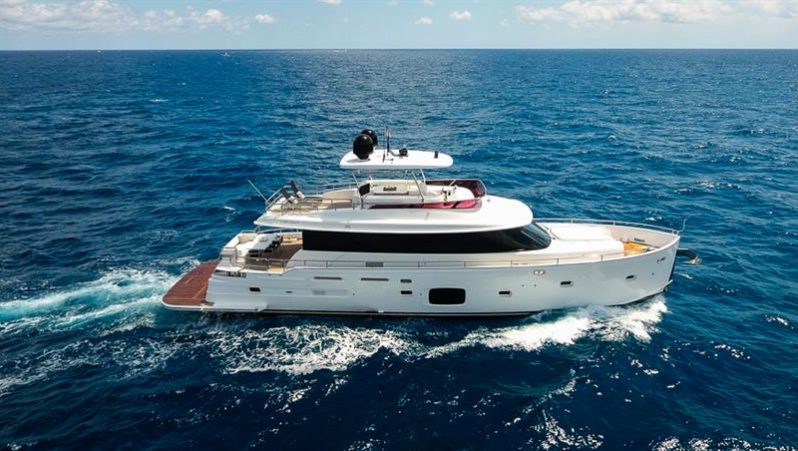
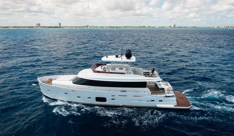
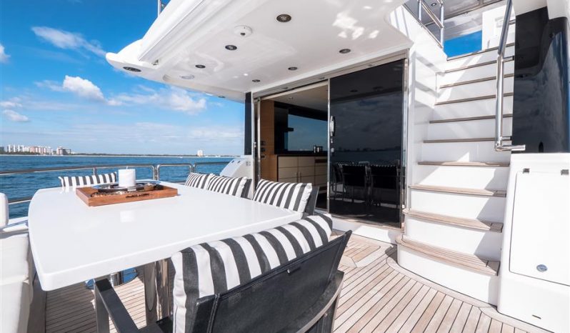
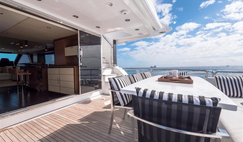
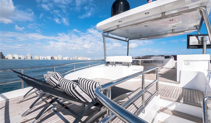
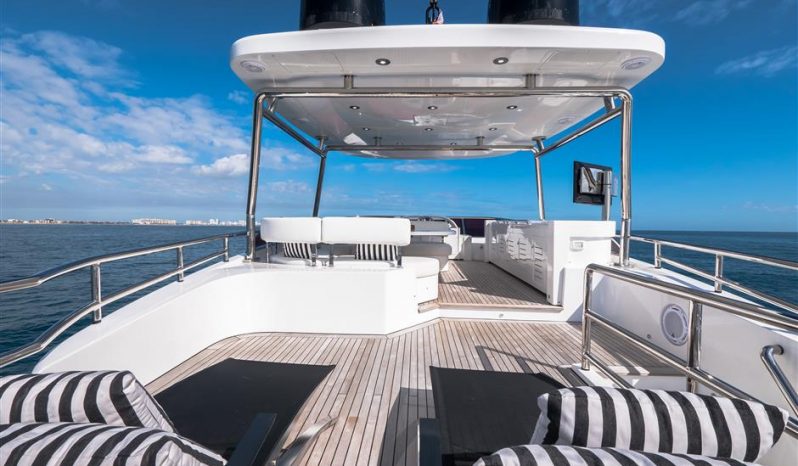
MAIN CHARACTERISTICS
The voltages on board are the following:
- 220 V a.c. single phase, 60 Hz, for: power circuits, lights in the engines room, neon lights, electrical outlets;
- 24 V c.c. with grounded negative for: engines starter, emergency circuits, spotlights, headboards and courtesy lights, little users, navigation lights, electronics
- 12 V c.c. with grounded negative for: generators starter
Electrical wiring is housed in metal or self-extinguishing closed PVC conduits. Electrical wiring is constructed with no flammable materials and with proper cross section related to the use. In the standard supply two extra conduits 40mm diameter from the hard top to the technical panel under the wheel house
The main control panels are located in the aft quarter’s lobby and in the wheelhouse. Secondary electrical panels are installed in all areas of the yacht
All equipment has ground junctions with adequate cords and braiding of copper with proper cross section.
One ground system has the following functions: ground system for machinery, sea water intakes, etc..; ground system for electrical circuits, which joins all control panels and electrical equipment. The ground system is made up by two copper straps all along the length of the yacht, connected to 2 aft zincs
POWER SOURCES GENERATORS
N° 2 20kW Kohler 220V/60Hz/ single phase generators, with 20 kW/20kVA/cosj = 0.8 power located in the engine room, hour meter and mounted on silent blocks, sound shield boxes, control panel and 12 V d.c. starter
Remote starter
SHORE PLUGS
N° 2 63A 220V shore plugs, located on transom, each connected to on board electrical system with a galvanic insulator
BATTERIES
Service and emergency batteries: n° 1 group of gel batteries 540Ah a 24Vcc, located in the cabinet underneath the helm station, for part of the lighting, signaling, little users, and emergency
n° 1 group of leaded batteries with 200Ah a 24Vcc for starting main engines. These batteries are high instant zap capacity
n° 2 groups of leaded batteries with a total capacity of 105Ah a 12Vcc. each one for generators starter. These batteries are high instant zap capacity
RECHARGING SYSTEMS
Two 24Vcc/75A automatic Mastervolt battery charger for service batteries
One 24Vcc/25A automatic Mastervolt battery charger for main engines starting batteries
One 12Vcc/25A automatic Mastervolt battery charger for generators starting batteries During navigation, engines alternators will charge each engine starter batteries
During navigation, genset alternators will charge each genset starter batteries
LIGHTS AND SOCKETS
220V a.c. for the engines room and technical areas made by IP65 lamps
24V c.c. for internal lights, the engines room emergency lights and for all external lights
internal lights are LED; external lights are LED or halogen
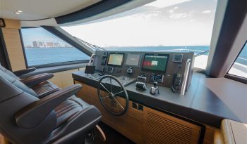
WHEELHOUSE:
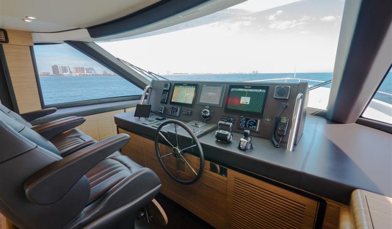
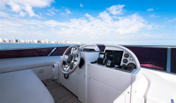
RAYMARINE E95 — 9’’ radar/chart plotter
RAYMARINE I70 multifunction display
RAYMARINE PT70R autopilot
RAYMARINE VHF RAY 240E DSC classe D
COMPASS White Star BP2.
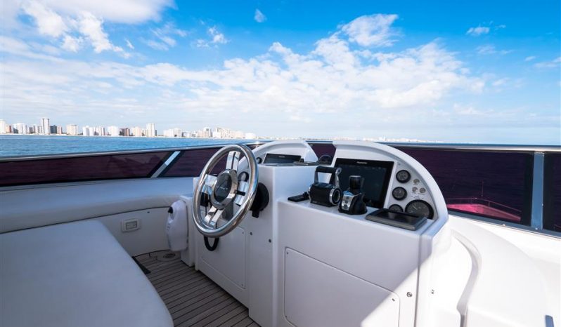
FLY:
RAYMARINE E95 — 9’’ radar/chart plotter
RAYMARINE I70 multifunction display
RAYMARINE PT70R autopilot
RAYMARINE VHF RAY 240E KIT 2nd STATION COMPASS Zenith BZ1/3-143
HARD TOP:
N° 1 Antenna PATHFINDER OPEN ARRAY 48” 4 Kw
N° 1 ANTENNA RAYMARINE VHF (V/067)
N° 1 Antenna GPS RAYSTAR 130
BILGE SYSTEM
(5) e/pumps 24Vcc (90lt/min to 5m H2O) bilge positioned to cover each compartment (1 x crew area, 1 x engine room, 2 x owner cabin, 1 x bow area). The pumps’ controllers and alarms are located in the wheelhouse on the “touch screen” and on the main electrical panel
Emergency suction in engine room, connected to the starboard engine sea intake
Copper and pvc-c pipes.
FIRE ALARM AND SAFETY SYSTEM
(12) portable extinguishers in all the areas of the yachts as follow:
-(3) 2 kg C02 extinguisher
-(6) 1 kg powder extinguishers
-(3) 2 kg powder extinguishers,
Centralized fire extinguishing system (FM200) in engine room
(1) extinguisher cylinder w/ handle for activation
Electronic box 12/24Vcc to stop air extractor in engine room, fuel decanting pump, generators and main engines
Alarm fire system in the helm station with sensor located in engine room
Two sea water fire hoses: one placed in the cockpit cabinet starboard side, one placed in the chain storage at bow
FUEL SYSTEM
(2) tanks in GRP, located midship: 7.500 l. total capacity (5250 l Main tank, 2250l daily tank). Each tank is provided with stainless steel AISI 304 breather pipe and electric sensor for level monitoring
Fuel tanks levels are visible on the touchscreen and on the main electrical panel. Double racor filters for engines, Racor filter for generators
Fuel filling operation is carried out through inlets placed on each side of the superstructure connected with the structural tank only
The decanting between the structural tank and the daily tanks can be realized through e/ pump (75lt/min to 7m H2O) or the emergency manual pump (24lt/min to 30m H2O)
The decanting e/pump controllers are in the main helm on the “touch screen” and on the principal electrical panel
FRESH WATER SYSTEM
System can be fed by the tank placed at bow (capacity:1400 lt) or by the shore connection on stern
Two e/pumps, one 220V (55lt/min), one 24V (55lt/min), pump water from tank to all the sinks, showers, bidet, galley and fly’s sinks, electrical appliances
Water heater with 100lt (26,8 US gls) maximum capacity, placed in VIP cabin bilge WC flushing
Active carbon filters on the shore water connection
Level monitoring on touch screen and on main electric panel
Predisposition for water maker
GREY AND BLACK WATERS SYSTEM
The two systems are structured as follows:
(1) tank 1450 lt (381US gls) for both grey and black water, placed forward of the fuel tank to collect showers, bidet, sinks, appliances (washer, dishwasher..) fancoils and WC discharges. The tank is provided with breather pipe, no-smell strainer, and with electric level sensor
The tank’s emptying comes manually outboard through (1) e/pump 230 Vac (45lt/min to 9m H2O). Pump controls are in the main electric panel and in the motronica
The tank’s emptying comes out ashore also through the dedicated hose placed aft on the transom
(2) Collecting tanks for grey water are placed as follows:
-(1) in the crew area to collect shower, sink, fancoil and washer discharge
-(1) in the owner cabin to collect shower, sink, bidet, fancoil and galley sink discharge
SEA WATER SYSTEM
(6) main bronze sea water intakes with valve and filter: (2) for generators, (2) for engines, (1) for the sea fire extinguisher manual pump and the air conditioning unit e/pump, (1) for the main sea fire extinguisher e/pump and for water maker predisposition
Sea water fire system made up of an E/P 220V (180lt/ min to 14m H2O ), placed in the technical area, engine room and connected to (2) hoses on main deck, one at bow and the other one at aft. The pump control is located in the main electric panel, in the main helm, on the fly and on starboard side of the superstructure area
Part of the main engines cooling water is used to cool gear box, the shaft seals, the bow thrusters oil and the raisers for gas discharge
Chain washing with sea water supplied by the same pump of firefighting system
AIR CONDITIONING, VENTILATION, AND EXTRACTION SYSTEM
Water circulation A/C conditioning system with two compressor chiller units placed in the engine room. Fan-coil displaced in every part of the boat, with independent controller of the temperature
salon/galley: 3 x 12.500btu/h fancoil wheelhouse: 2 x 16.000btu/h fancoil owner cabin: 2 x 9,200btu/h fancoil
starboard guest cabin: 1 x 9.200btu/h fancoil port guest cabin: 1 x 6.200btu/h fancoil
VIp cabin: 2 x 6.200btu/h fancoil Crew lobby: 1 x 6.200btu/h fancoil Crew cabins: 2 x 4.480btu/h fancoil
Centralized electric extractor (max 200m3/h) for the guest heads, set by (1) E/Extractor, controlled through the ignition of the light of each head
Centralized electric extractor for the secondary electrical panels, set by (1) E/Extractor (max 260m3/h)
Electric extractor for the crew head and aft technical area, set by (1) E/Extractor (max 600m3/h), controlled through the ignition of the lights
Electric extractor for the windscreen demisting system, set by (1) E/Extractor (max 600m3/h) The ventilation of engine room works through natural ventilation and (2) E/Extractors (220V max 5460m3/h)
MAIN ENGINES EXHAUST SYSTEM
AISI 304 exhaust piping with AISI 316L raisers, built according to engines manufacturer prescriptions
Generators exausts on the hull sides
ELECTRO-HYDRAULIC
One electro-hydraulic unit for rudders, 24Vcc
One electro-hydraulic unit for gangway and swimming platform, 220 Vac/24Vcc
One pump connected to the starboard main engine for the bow thruster, provided with 50lt oil tank and heat exchanger

